NOR Gate Logic Gates Tutorial
The AND gate is a basic digital logic gate that implements logical conjunction (∧) from mathematical logic - AND gate behaves according to the truth table. A HIGH output (1) results only if all the inputs to the AND gate are HIGH (1). If not all inputs to the AND gate are HIGH, LOW output results.
NOR Gate as Universal Gate YouTube
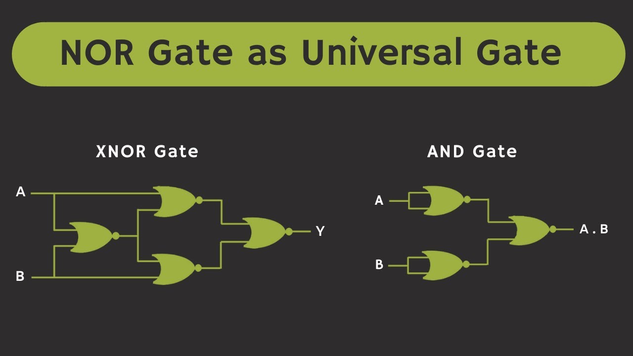
A NOR gate or a NOT OR gate is a logic gate which gives a positive output only when both inputs are negative. Like NAND gates, NOR gates are so-called "universal gates" that can be combined to form any other kind of logic gate.

NOR Gate as Universal Gate As NOT and OR Gate YouTube
2. AND Gate: AND gate is a three terminal device in which two terminal is for the input and one is for the output purpose. The working of the logic gate is such that we obtain binary 1 at the output if and only if both the input is at the binary1.

Introduction to logic gates projectiot123 is making esp32,raspberry pi,iot projects
A NOR gate, which stands for NOT-OR, is a combination of an OR gate and a NOT gate. It is a universal gate, meaning that any other logical function can be constructed entirely with NOR gates. How NOR Gates Work. The NOR gate is a digital logic gate that operates on the principles of Boolean algebra. Its output is 'true' or '1' only when.

NOR Gate Logic Gates Tutorial
NAND to NOT: - The algebraic expression of the NAND to NOT gate conversion will be the same as the NOT gate. So the algebraic conversion of the NOT gate is:- Y=A' NOR to OR: - The algebraic expression of the NOR to OR gate is: A+B NOR to NAND: - The algebraic expression of the NOR to NAND gate is A'+B' . NOR to XOR: -

CircuitVerse Realization of all GATE using NOR Gate
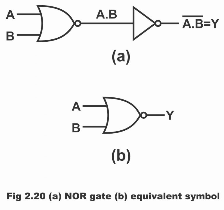
A NOR gate ("not OR gate") is a logic gate that produces a high output (1) only if all its inputs are false, and low output (0) otherwise. Hence the NOR gate is the inverse of an OR gate, and its circuit is produced by connecting an OR gate to a NOT gate.
PPT Universal Gate NOR PowerPoint Presentation, free download ID3584919
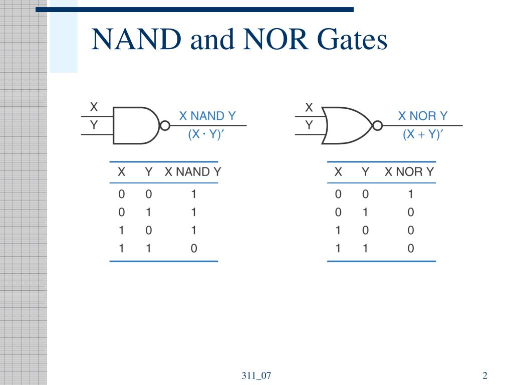
The equation for a NAND gate is C = A·B. The equation for a NOR gate is C = A+B. Even if you never plan to design digital hardware, it is good to appreciate why inverting gates (NAND and NOR) are preferred for logic design. The simplest gates are naturally inverting. Simple gates are faster, smaller, and use less power.
Logic NOR Gate Working Principle & Circuit Diagram
What is an AND gate? Truth table for AND gate/operator What is an OR gate? Truth table for OR gate/operator What is an inverter or a NOT gate? Truth table for NOT gate/operator What is an EXOR gate (XOR)? Truth table for EXOR gate/operator What is an EXNOR gate (XNOR)? Truth table for EXNOR gate/operator What is a NAND gate/NAND logic?
Cmos Circuits For Nand Nor Gates Wiring View and Schematics Diagram
NAND XNOR NOT Logic Gates in Computer Code Wrapping up Logic gate: a cool term, but what does it mean? This article will introduce the concept of a logic gate as well as describe how each specific logic gate (OR, AND, XOR, NOR, NAND, XNOR, and NOT) works. What Is a Logic Gate? First, it's important to realize that logic gates take many forms.

Pin on Electronic
There are seven basic logic gates: AND, OR, XOR, NOT, NAND, NOR and XNOR. The AND gate is named so because, if 0 is false and 1 is true, the gate acts in the same way as the logical "and" operator. The following illustration and table show the circuit symbol and logic combinations for an AND gate.

CircuitVerse OR GATE USING NOR GATE
1 A 1 0 B 0 AND is a Boolean operation, an operation that takes values that are either "true" or "false", and then outputs "true" or "false" based on a logical manipulation of those inputs. In logic gates, we consider 1 to be true and 0 to be false.

Digital Logic NOR Gate(Universal Gate) All About Engineering
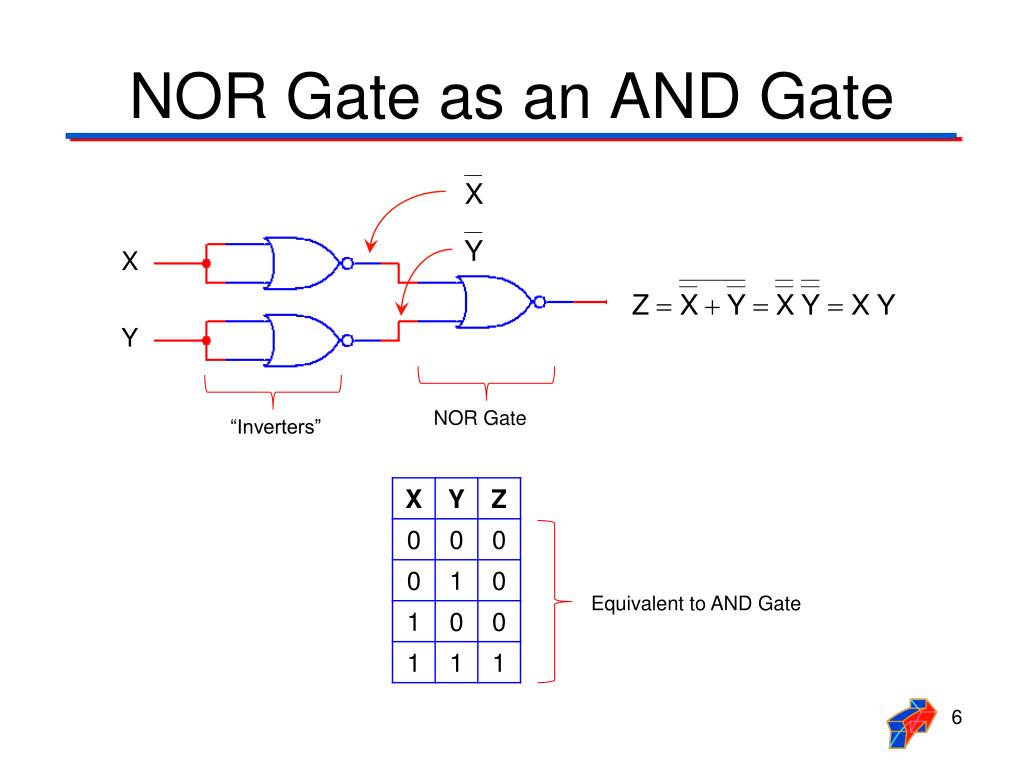
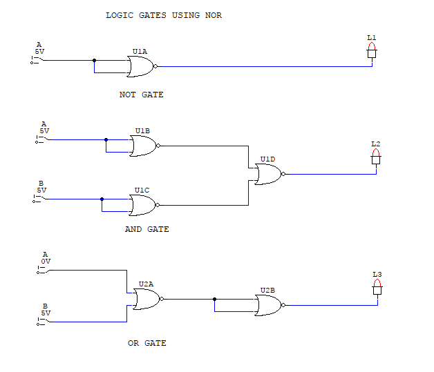
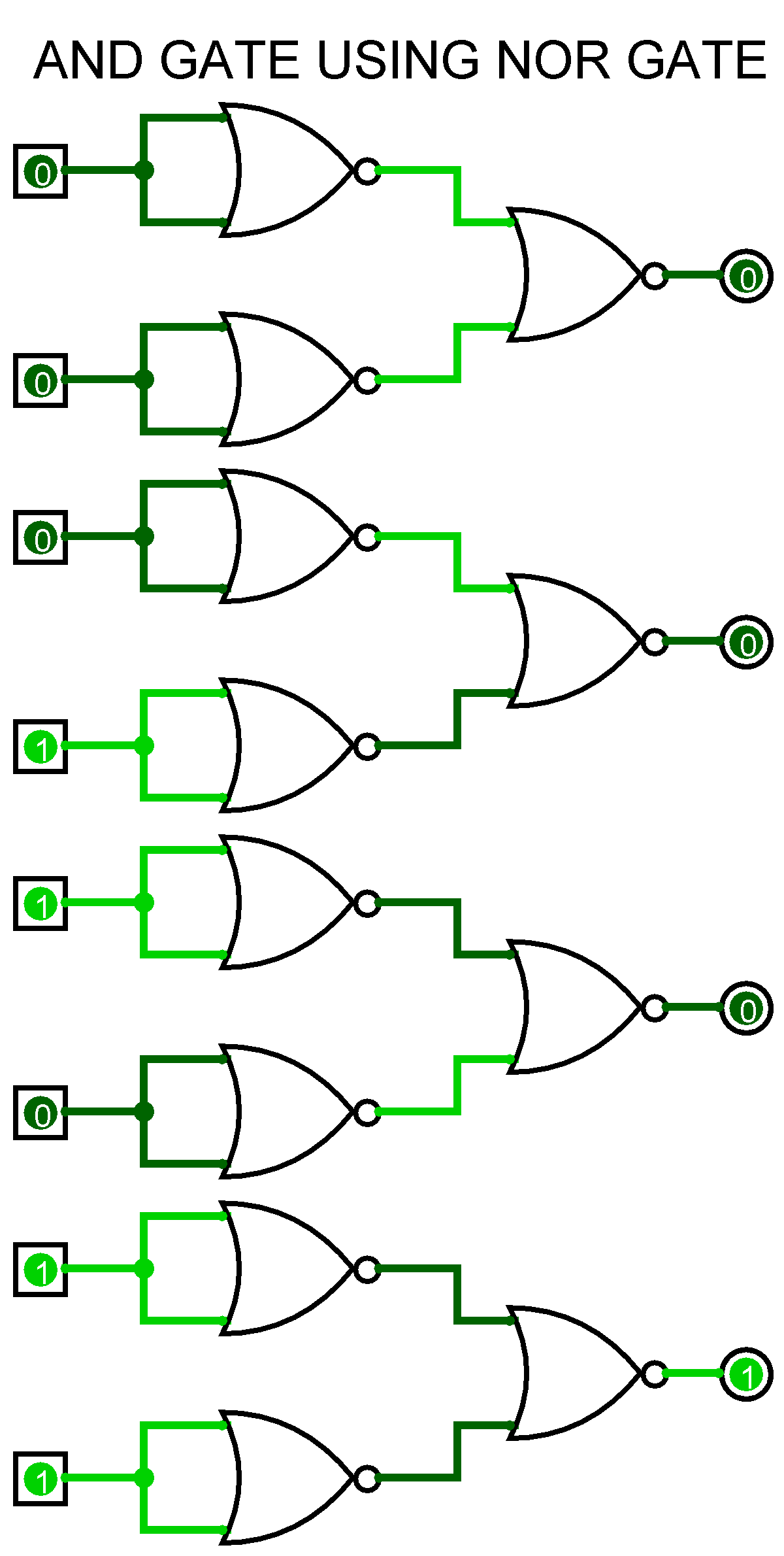
To study and verify the Implementation of AND Gate using NOR gate. Learning Objectives To understand the behavior and demonstrate the Implementation of AND Gate using NOR gate. To apply knowledge of the fundamental gates to create truth tables. To develop digital circuit building and troubleshooting skills.
PPT NAND and NOR Gates PowerPoint Presentation, free download ID4401548
A NOR gate, sometimes known as a "NOT-OR" gate, consists of an OR gate followed by a NOT gate. This gate's output is 1 only when all of its inputs are 0. Alternatively, when all of the inputs are low, the output is high. The Boolean statement for the NOR gate is Y= (A+B)' if there are two inputs A and B.
To Study and Verify the Truth Table of Logic Gates. AHIRLABS
When the output of OR gate is NOTed or inverted then it is called the NOR gate. NOR means NOT OR. NOR gate is the combination of an OR gate and a NOT gate. The output is 1 or HIGH when only both input is 0 or LOW. Otherwise, the output is 0. The boolean expression for the NOR gate is expressed as given below This is read as X is equal to A plus.
To Study and Verify the Truth Table of Logic Gates. AHIRLABS
NAND gate NOR gate According to the exclusive type of logic gates Exclusive - OR gate (Ex-OR gate) Exclusive - NOR gate (Ex-NOR gate) According to the single input type of logic gates Hex buffer NOT gate (Inverter) #1 AND Gate The AND gate is often called an "all-or-nothing gate". The AND gate consists of 2 or more input signals.
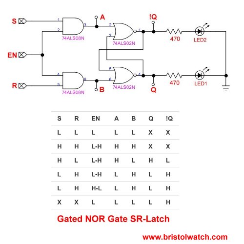
Tutorial NOR Gate SR Latch Circuit
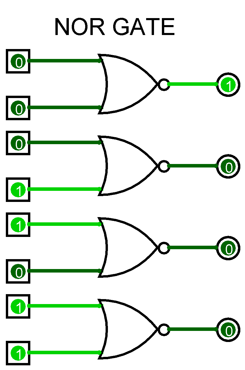
The NOR gate is a digital logic gate that implements logical NOR - it behaves according to the truth table to the right. A HIGH output (1) results if both the inputs to the gate are LOW (0); if one or both input is HIGH (1), a LOW output (0) results. NOR is the result of the negation of the OR operator.
